
Abstract
This paper introduces a novel five-port, three-input, dual-output isolated bidirectional dc-dc converter (FPIBC) topology with an effective controller for power-sharing and voltage-balancing in bipolar dc microgrids (BPDCMGs). The proposed converter acts as the interface for the integration of a hybrid generation system comprising a solid oxide fuel cell (SOFC), a photovoltaic (PV) system, and a battery into BPDCMGs. It employs a reduced number of circuit elements compared with similar multiport converter topologies suggested for BPDCMG applications. Symmetrical bipolar output voltages are ensured by a voltage-balancing circuit composed of a fully controlled switch and four diodes. The FPIBC is equipped with different controllers for output voltage regulation and balancing, power sharing, maximum power point tracking of the PV, the optimum operating region of the SOFC, and constant-current, constant-voltage charging of the battery. To verify the viability and effectiveness of the proposed system, a simulation model was developed with a 4.2 kW SOFC, a 3.7 kW PV, and a 140 V 10.8 Ah battery in MATLAB/Simulink. The performance of the FPIBC was evaluated through extensive case studies with different operational modes, including battery charge/discharge states and SOFC and PV parameter changes under varying load conditions. In addition, the proposed system was examined using a daily dynamic load profile. According to the simulation results, a peak efficiency of 97.28% is achieved and the voltage imbalance between the output ports is maintained below 0.5%. It is shown that the FPIBC has advantages over previous converters in terms of the number of ports, number of circuit elements, bipolar output voltage, bidirectional power flow, and efficiency.
Keywords: dc microgrid; multiport converters; renewable energy integration; voltage balancing
1. Introduction
Power generation systems based on renewable energy sources (RESs), such as fuel cells (FCs) and photovoltaic (PV) systems, have attracted attention due to the rapid depletion of fossil fuels and environmental pollution problems. Owing to their intermittent power generation, RESs are generally utilized with energy storage units (ESUs), such as batteries and supercapacitors, to provide an uninterrupted and stable power flow to loads. Microgrids, which may operate in grid-connected or island mode, have emerged as an efficient solution for integrating various RESs, ESUs, and loads. Recent studies have pointed out that dc microgrids (DCMGs), in which RESs can be interfaced more easily than ac microgrids, are a significant alternative to conventional power networks. In addition to their advantages, such as high efficiency and reliability, DCMGs are of interest because of the absence of problems such as synchronization, harmonics, and reactive power [1].
To integrate multiple RESs and ESUs simultaneously into DCMGs, a large number of independent power electronic converters would be necessary. Nevertheless, such a configuration has a low efficiency and a high cost and leads to difficulties with centralized control [2]. Multiport converters (MPCs) have recently gained prominence due to their advantages of a lower number of switches, lower costs, a higher efficiency, a higher power density, and requiring less complexity in their control. It has been reported in the literature that MPCs can be classified into two fundamental categories: non-isolated and isolated [3,4]. Non-isolated MPCs, derived from buck, boost, and buck-boost converters, have the advantages of a more compact design and a high power density [5]. These types of MPCs are suitable for low-voltage DCMG applications as the voltage conversion ratio between the ports is not too high, but they are less reliable due to the lack of a high-frequency transformer (HFT) [6,7]. In Refs. [3,8,9,10,11,12,13], non-isolated, three-port converter (TPC) topologies are presented. Askarian et al. [3] suggest the use of a non-isolated bidirectional TPC with a low number of components to interface a PV panel and a battery to a dc nanogrid. Chandran et al. [8] introduce a non-isolated TPC derived from a combination of Zeta and KY converters fed by a hybrid PV–battery system. Danyali et al. [9] designed a non-isolated, high-gain, soft-switching TPC based on a switched-capacitor (SC) voltage multiplier that integrates a battery and renewable sources such as PV or FC. In Ref. [10], a Cuk-based, non-isolated TPC with the control of a PI-lead compensator is proposed. In Ref. [11], a non-isolated, boost-based TPC structure is presented in which the PV and battery are used as the main and support sources and can operate in three different modes depending on the status of the input and output ports. In Ref. [12], a non-isolated, high-voltage-gain TPC employing coupled inductor and switched-capacitor topologies is presented. Another high-voltage-gain, non-isolated TPC topology using a coupled inductor with three windings is recommended in [13] for renewable energy applications. Isolated MPCs, commonly formed from half-bridge (HB) or full-bridge (FB) topologies, are utilized in medium-voltage DCMGs for critical applications that require isolation. These types of MPCs provide galvanic isolation, more flexible voltage levels using HFT, and an easier implementation of soft switching [14]. A great deal of research has been conducted on the design of isolated MPC topologies. In Ref. [15], bidirectional isolated MPCs, suitable for use in modern aerial vehicles, are reviewed. In Ref. [16], an interleaved HB TPC is proposed to interface a 500 W PV–battery hybrid power system (PVBHPS). In Ref. [17], an isolated TPC that incorporates an adaptive neuro-fuzzy interference-based maximum power point tracking (MPPT) controller, with an improved efficiency and voltage gain, is presented. In Ref. [18], an isolated, bidirectional, high-gain TPC utilizing a current-fed dual-active-bridge (DAB) structure has been developed to integrate low-voltage battery-supercapacitor-based hybrid energy storage systems into a DCMG. In Ref. [19], a TPC based on an inductor–inductor–capacitor (LLC) resonant converter topology is presented to interface a PVBHPS with a DCMG. In Ref. [20], a four-port converter with six active switches has been designed, inspired by a TPC including two interleaved buck-boost converters. A four-port converter consisting of fewer components is presented in [21] for electric vehicle applications. Vettuparambil et al. suggested isolated four-port [22] and five-port [23] converters based on split dc-link active bridges to interface different PV modules and a battery with a 380 V DCMG.
To improve their power quality and reliability, bipolar-type DCMGs offering two voltage levels in a three-wire dc line (positive, neutral, and negative) have been introduced [24]. Bipolar dc microgrids (BPDCMGs) are preferred, particularly in data centers, as they can feed critical loads using the other two remaining wires when an abnormal condition or fault occurs in one wire [25]. Although BPDCMGs provide advantages in terms of their high efficiency and power-carrying capacity, the voltage differences between the upper and lower terminals, the voltage stability, and power flow management are issues that need to be investigated [26]. One of the crucial concerns encountered in BPDCMGs, and one that has been addressed in several studies in an attempt to mitigate their adverse effects on power quality, is the voltage imbalance. To acquire symmetrical bipolar output voltages, series-connected power converters or voltage balancers have been proposed. In Ref. [27], a dc–dc converter using only one active switch is developed. In Ref. [28], a three-level neutral-point-clamped (NPC)-based voltage balancer circuit is presented with improved switching modulation. In Ref. [29], a bidirectional dual-buck-boost voltage balancer with direct coupling is put forward. In Ref. [30], different types of converters, such as buck-boost, interleaved buck-boost, cuk, and super sepic/zeta converters, are employed as voltage balancers. In Ref. [26], a three-level bipolar bidirectional dc–dc boost converter has been designed to perform a voltage-balancing function when the trans-z-source inverter, which interlinks the BPDCMG to the ac grid, is disconnected. In Ref. [31], a bidirectional capacitor–inductor–inductor–capacitor (CLLC) dc–dc converter integrated with two additional inductors is recommended to determine the voltage imbalances in the BPDCMG.
It was brought to our attention that MPCs developed for BPDCMGs in recent studies perform voltage-balancing functions. In Ref. [32], a boost-SEPIC-type interleaved converter that can compensate for voltage imbalances by reducing the neutral line current in a low-voltage BPDCMG is suggested. In Ref. [33], a TPC based on a buck-boost converter is provided to perform both battery management and voltage balancing in a BPDCMG. In Refs. [25,34], a TPC is recommended for integrating a battery system with a BPDCMG and mitigating voltage imbalances. In Refs. [2,6], four-port non-isolated dc–dc converter topologies are presented for interfacing a PVBHPS and PV–FC sources with low-voltage BPDCMGs. Because the converter in [2] has an inherently symmetrical bipolar output feature, no additional voltage-balancing circuit or balancing control is required. It is highlighted that the converter in [6] has fewer circuit elements in its topology than other four-port converters used in BPDCMGs. In Ref. [35], an isolated four-port converter, namely an FB interleaving bidirectional buck/boost + semiactive rectifier, is proposed. In Ref. [36], the design and analysis of a T-type isolated four-port converter are presented for interfacing an FC/battery electric vehicle-to-home (V2H) system. In Ref. [14], an isolated five-port converter that combines DAB and NPC topologies is offered for medium-voltage BPDCMG applications. In that study, the output voltages are balanced by benefiting from the NPC circuit located on the secondary side of the proposed topology and by developing a control scheme in accordance with the modulation technique. Although an additional voltage-balancing circuit is not employed in this topology, there are a large number of switching elements owing to the NPC’s structure, which increases the cost and power loss.
In this paper, a novel five-port isolated bidirectional dc–dc converter (FPIBC) topology is proposed for the integration of a hybrid power generation system consisting of a solid oxide fuel cell (SOFC), PV, and a battery into a BPDCMG. The main contributions of the paper are outlined as follows:
(i)
The proposed converter is cost-effective and highly efficient, as it employs fewer active switches than other three-input, dual-output isolated converters presented in the literature.
(ii)
It has a bidirectional port for the battery, which can not only feed the load group, but can also be charged by both the PV and SOFC.
(iii)
Because the voltage-balancing circuit comprises an active power switch with four diodes in the FPIBC topology, symmetrical bipolar output voltages are obtained. The FPIBC is capable of balancing the positive and negative terminal voltages, even in the case of a severely unbalanced load distribution with a power difference of up to 1000 W.
(iv)
The FPIBC can manage bidirectional power flow by charging and discharging the battery considering the available power of the PV and SOFC with respect to the load demand.
(v)
The functionality of the proposed system is demonstrated and verified by three extensive simulation case studies under changing load conditions. It has been concluded that the proposed FPIBC is applicable and can be a good candidate for interfacing RESs and ESUs into BPDCMGs efficiently compared to traditional converters.
The remainder of this paper is arranged as follows: Section 2 addresses the proposed FPIBC topology and its operation scenarios. Section 3 describes the design of the controller of the proposed system. In Section 4, the simulation results for three different case studies are presented and a discussion is provided. Finally, conclusions and significant contributions are highlighted in Section 5.
2. Proposed FPIBC System
2.1. Power Circuit
The FPIBC topology, which consists of two FB converters, a resonant tank, and a voltage-balancing circuit, is illustrated in Figure 1. In the proposed structure, hybrid generation sources composed of a PV, an SOFC, and a battery are used as input ports. On the primary side, the RESs are connected to the FB converter via inductors L1 and L2, whereas no inductor is employed to connect the ESU. Connection via inductors provides boost characteristics for SOFC and PV output voltages. A series resonant inductor Lsr and a series resonant capacitor Csr are inserted at the output of the FB converter. Galvanic isolation between the input and output ports is achieved using an HFT with a unity turn ratio (n = 1). A voltage-balancing circuit formed from an active power switch (Q5) and four diodes (Dx, Dy, Dz, and Dt) is utilized to compensate for the imbalances that occur in the output voltages on the secondary side.
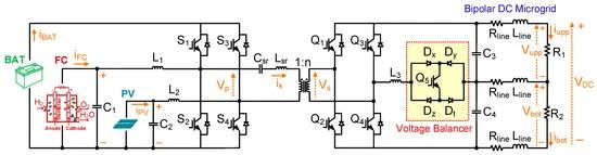
Figure 1. Power circuit diagram of the proposed FPIBC.
Bidirectional power flow on the primary side is assured by charging/discharging the battery, depending on the load demand and the available power of the PV and SOFC. There is a boost converter relationship between the PV and the battery and the SOFC and the battery, respectively. S1, S2 and S3, S4 are the pairs of complementary switches on the primary side. Boost conversion between the PV and the battery is realized using the boost inductor (L2), active switch S4, the diode of S3 switch, and the filtering capacitor (C2). Similarly, boost conversion between the SOFC and the battery is performed with inductor L1, active switch S2, the diode of S1, and the filtering capacitor (C1). In the steady state, the following equations are derived by applying a voltage–second balance across L1 and
(2)where Vpv, Vfc and Vbat are the PV, the SOFC, and the battery voltages, respectively. “dpv” defines the duty cycle of the primary side switches (S3, S4), while “dfc” indicates the duty cycle of the primary side switches (S1, S2).
Resonant converters containing a network of inductors and capacitors called “resonant tanks” are used to drastically reduce switching losses with ZVS and zero-current switching (ZCS) capabilities. Although there are many approaches for the control of resonant converters, the most commonly used method is the frequency control technique [37]. In the frequency control method, an efficiency drop occurs due to sharp changes in the switching frequency, and the control/design is complicated because the switching frequency varies over a wide range [37,38]. To avoid these disadvantages, a phase shift modulation technique with fixed-frequency operation is employed. In this study, a series resonant tank is connected to the primary side of the proposed converter, and the system is operated at a switching frequency close to the resonant frequency of the tank.
A simplified equivalent circuit with respect to the forward power flow direction from the primary to secondary side of the proposed FPIBC is shown in Figure 2. Based on the simplified equivalent circuit, the steady-state characteristics of the bidirectional dc–dc converter with a series LC resonant tank can be derived from the fundamental harmonic approximation [39]. Vp,1 and Vp,2 are the fundamental components of the square waves Vp and Vs, as provided in Equations (3) and (4), respectively.
(3)
????????1(????)=4????????????????????sin????????????,
(4)
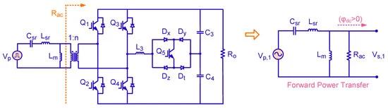
Figure 2. Illustration of equivalent circuit between the primary side and secondary side of the FPIBC.
The dc gain in the resonant converter, Kf, when φdc > 0 (forward power transfer) can be obtained as given in Equation (5) [40].
where ws is the angular switching frequency, Lm represents the magnetizing inductance of the transformer, and Rac denotes the reflected load resistance value, which is calculated below:
The load resistance R0 for the forward power transfer mode can be formulated as in Equation (7):
The dc gain in the resonant converter given in Equation (5) can be rearranged as follows when the turns ratio is equal to unity (n = 1):
In Equation (8), Q is the quality factor, λ is the ratio of the magnetizing inductor to the resonant inductor, and Fx is the normalized switching frequency. These parameters, which affect the dc voltage gain in the resonant converter, are described by the following equations:
fr is the resonant frequency, which is expressed as:
The active power is delivered through a phase shift (φdc) between Vp and Vs. The power transferred from the primary side to the secondary side of the proposed converter can be calculated from either side. The output active power can be defined as [41]:
2.2. Power Sharing Modes
The proposed converter operates in three different modes with respect to the power flow scenarios and load power requirements, as illustrated in Figure 3. The operation mode is determined by considering the available power of the PV, SOFC, and battery at the load demand. According to the mode determination flowchart, it is first determined whether the PV produces power. If PV power is not available, the proposed converter operates in mode 3, in which the battery and SOFC can supply the power demanded by the load. If the PV produces power, the converter operates either in mode 2 or mode 1.
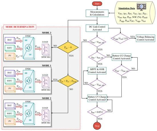
Figure 3. Flowchart of overall control algorithm with the power flow scenarios.
Mode 1: Although solar radiation exists in this mode, the PV power is less than the power demanded by the load on the BPDCMG side and is not sufficient to supply the load alone. The load is fed by both the PV and SOFC if the overall power of the PV and SOFC exceeds the load demand. In this case, the battery is charged to absorb the surplus renewable energy. A power transfer scenario is defined as T for different operation modes m1, m2, and m3, and the following formula describes mode 1 and the power flow between ports.
(12)
Mode 2: In this mode, the load demand is greater than the total amount of PV and SOFC power. The excess power should be provided by the battery, which is discharged from its previous charged state to support the RESs. Therefore, the load is fed by the PV, SOFC, and battery. The operating conditions of mode 2 and the power flow between the ports in this mode are given by the following equation:
(13)
Mode 3: This mode corresponds to the absence of available solar power, and thus, the load is fed by both the SOFC and battery. Since the SOFC power is not sufficient to supply the load alone, the battery is discharged by the proposed converter to assist the SOFC. The power flow between ports is calculated using the following equation:
(14)
3. Controller Design
In this section, an effective multi-loop control scheme for the proposed FPIBC is explained. The main objectives of the controller are to provide bidirectional power flow, charge/discharge the battery using the constant current/constant voltage (CC/CV) algorithm, extract the maximum power from the RESs, and mitigate the imbalances between the bipolar output load voltages. The proposed controller, illustrated in Figure 4, consists of six different control loops: MPPT for the PV, an optimum operation region (OOR) for the SOFC, CC and CV for battery charging, dc-link voltage regulation, and output voltage balancing. The system operates adaptively and allows instantaneous switching between the control loops.
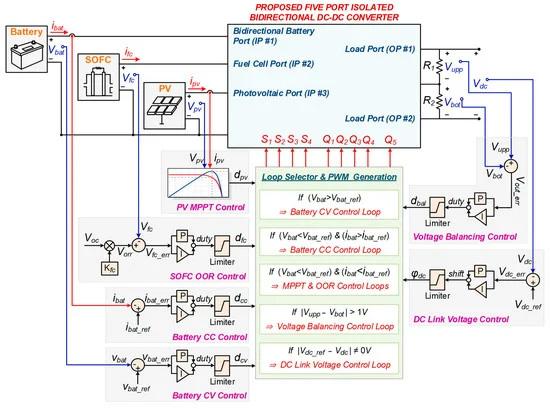
Figure 4. Multi-loop controller scheme of the FPIBC.
The FPIBC provides power flow from the PV, SOFC, and battery to the load side by considering the variation in ambient temperature, the instantaneous states of solar irradiation of the PV, and the operating temperature (OT) and fuel pressure (FP) of the SOFC. The first priority during energy flow is to ensure uninterruptible power to the loads. Therefore, the power flow between the primary side energy units is also controlled while transferring power from the primary side to the secondary side. During this operation, the dc-link voltage controller constantly regulates the output voltage by performing single phase shift (SPS) modulation. The dc-link voltage controller aims to maintain the output voltage constant at 200 V (Vdc_ref) using a proportional integrator (PI) controller, which determines the phase shift (φdc) between the primary and secondary switches (S1–S4 and Q1–Q4). Traditionally, the dc-link voltage controller generates switching signals with a constant duty cycle (50%) and a 180-degree phase shift between the two legs to provide a square-wave ac voltage across the transformer terminals. However, the proposed controller makes it possible to regulate the power flow between the primary energy units by adjusting the duty cycles (dpv, dfc, dcc, and dcv) of the switches located on the legs. While the dc-link control loop continuously regulates the output voltage, the controllers of the PV-MPPT, SOFC-OOR, CC, and CV are enabled according to the instantaneous power production capability of the PV and SOFC.
When the instantaneous power values produced by the PV panels and SOFC do not meet the demand of the load/battery, the controller enables the PV-MPPT and SOFC-OOR control loops to extract the maximum power from the PV and SOFC. The best operational point of the PV to produce maximum power is determined using the MPPT method based on Perturb and Observe (P&O) [42], which is the most frequently used technique because of its ease of operation and reduced computational load. The MPPT controller continuously monitors the voltage and current of the PV system and regulates the voltage according to the power–voltage curve by adjusting the duty cycle (dpv) of switches S3 and S4. While the duty cycle value of the first leg of the primary side H-bridge is regulated by the P&O MPPT algorithm, the duty cycle (dfc) of the second leg (S1 and S2 switches) is regulated by the OOR technique based on the fractional open-circuit voltage (FOCV) [42]. Flowcharts of the P&O-based MPPT and FOCV-based OOR algorithms are shown in Figure 5a,b, respectively. The SOFC-OOR control loop determines the reference voltage of the SOFC (VORR) using the following formula:
(15)where Kfc is the voltage factor and Voc is the open-circuit voltage of the SOFC stack. Typical values of Kfc vary within the limits of 0.7–0.8 [43], and the related parameter is assumed as 0.75 in the proposed controller. The reference voltage of the SOFC is compared with the actual voltage of the SOFC to calculate an error signal, which is then applied to the PI controller to generate the duty cycle (dfc) value.
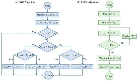
Figure 5. Flowcharts of the P&O-based MPPT and FOCV-based OOR techniques.
When the total instantaneous power supplied by the PV panels and SOFC meets the demand of the load/battery, the controller activates CC/CV charging algorithms to regulate the charging current of the battery and extend its service life. While the charging current (ibat) is kept constant at 5.4 A (i.e., 0.5 C) during the operation of CC charging, the charging voltage (Vbat) is kept constant at 161.4 V during the operation of CV charging. The PI controller is adopted to regulate the duty cycles of the primary switches, considering the differences in the reference/actual values of the current/voltage of the battery. As shown in Figure 3 and Figure 4, the excessive power of the SOFC and PV is transferred to the battery using the PV-MPPT and SOFC-OOR control loops if the charging voltage and current of the battery are less than their reference values. The CC control loop is enabled when ibat reaches a reference current value of 5.4 A (ibat_ref). Subsequently, Vbat increases to the reference value (Vbat_ref), and the battery is charged using the CV control loop until the charge current gradually decreases to 0.05 C.
The last control loop is the voltage-balancing control loop, which is advanced to compensate for the imbalances that occur between the bipolar output load voltages. Voltage-balancing control is achieved by adjusting the duty cycle of the Q5 switch. The switching position of the Q5 switch is crucial for the operation of the voltage balancer circuit. The output voltages Vupp and Vbot are continuously monitored to detect imbalanced conditions. When the voltage difference between the output ports (Vout_err) exceeds the hysteresis limit (1 V), voltage balancing control is activated. The PI controller produces the duty cycle (dbal) of the Q5 switch. In this manner, the voltage imbalance between the output loads is ensured to remain below 0.5%.
Table 1 lists the one-cycle switching patterns of the system. The proposed converter operates in 11 switching states, including all possible operating modes and imbalances. The switching positions associated with modes of operation are summarized, in which “0” and “1” represent the “OFF” and “ON” states of switches, respectively.
Table 1. Switching states and positions for one switching cycle.
4. Simulation Results and Discussions
The viability and effectiveness of the FPIBC were verified through simulation studies performed using MATLAB/Simulink software (2022b version). The dynamic properties of the system and all possible realistic scenarios are considered in the simulation environment. The ESR and ESL of the capacitors, the leakage inductance of the high-frequency transformer, the MOSFET characteristics, and the parasitic effects of the wires were modeled. The parameters of the simulation model are provided in Table 2. The performance of the proposed system and the designed controller is evaluated under three extensive case studies involving all modes of operation, dynamic load variations, and PV and SOFC parameter changes, which are presented in Table 3.
In the first case, the steady-state behavior of the FPIBC under different OT and FP values of the SOFC, its dynamic response during a sudden load change, and the transition from mode 1 to mode 2 were analyzed. Nevertheless, the voltage imbalance at the output ports of the FPIBC has not been addressed. Hence, the active powers of the upper and lower load groups (Pupp and Pbot) are equal at all time intervals. Solar irradiation and ambient temperature are considered constant at 400 W/m2 and 25 °C, respectively. Figure 6 shows the simulation results obtained for Case 1. The OT of the SOFC is 973 K until t = 5 s, and decreases to 923 K at t = 5 s. The FP of the SOFC is measured in the range of 1.35 bar, 1.15 bar, 1.0 bar, and 1.35 bar, respectively. As shown in Figure 6, the same power is approximately produced from the PV with the MPPT controller at every time interval because the parameters affecting the PV power are constant. However, the maximum power generated from the SOFC with the OOR controller is between 3627.92 W and 4199.02 W depending on the changes in OT and FP.
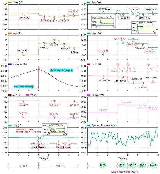
Figure 6. Simulation results of Case 1.
Figure 6 shows the power-sharing capability of the proposed converter when it operates in mode 1 (1 s < t < 4 s) and mode 2 (4 s < t < 8 s). In the time interval of 1–4 s, the battery is operating in charging mode because the total power of the PV and SOFC is greater than the load demand. The instantaneous power values of the PV, SOFC, battery, and load are 1507.09 W, 4199.02 W, −691.48 W, and 4800 W, respectively, at t = 2.5 s. The battery is charged with a nominal current of −4.53 A during the time interval of 1–4 s, and the SOC of the battery increases. The power demand of the load increases from 4800 to 6400 W at t = 4 s. The battery initiates discharging to support the RESs at t = 4 s, as the total amount of PV and SOFC power is not sufficient to meet the power demand of the load. The undershoot and settling time are 0.4847 V and 13.8 ms in the dc-link voltage during the load change at t = 4 s in Case 1. The current of the battery is positive when it is in discharging mode during the time interval of 4–8 s, and the SOC of the battery decreases over time. The results reveal that the dc-link voltage (VDC) is kept almost constant at 200 V and is not affected much by the load changes. An efficiency analysis of the proposed converter is performed considering the amount of generated electrical power from the PV and SOFC, the power absorbed/injected by the battery, and the power consumed by the load. The efficiency of the system varies between 95.41% and 96.42% for Case 1. The distribution of the calculated losses in the time interval of 6–7 s is shown in Figure 7. This figure was created using the results from one of the most comprehensive system-level circuit simulators for power applications.
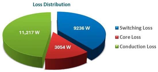
Figure 7. Simulation results of Case 1.
The second case explores the dynamic performance of the proposed converter in the case of a sudden change in solar irradiation and load transients. The different operational modes and the steady-state and dynamic responses of the FPIBC in Case 2 are depicted in Figure 8. The time intervals of 3–5 s and 6–8 s exhibit unbalanced load conditions. The OT and FP of the SOFC and the ambient temperature are assumed to be 973 K, 1.15 bar, and 25 °C, respectively. The solar irradiation is 600 W/m2 until t = 5 s and increases to 1000 W/m2 at t = 5 s. In the time interval of 1–3 s, the FPIBC operates in mode 1 and the battery is charging. As can be seen in Figure 8, the PV and the SOFC produce 2259.85 W and 4117.89 W at t = 1.5 s when the MPPT and OOR controllers are active. At that time, the instantaneous power values of the battery and the load are −1784.95 W and 4400 W. In the time interval of 2–3 s, the charge current of the battery is limited to 0.5 C (~5.4 A) as the CC control loop is enabled. During that time interval, the PV current decreases from 23.35 A to 12.29 A, and the PV voltage increases from 96.77 V to 111.72 V since the MPPT controller is disabled. Hence, it has been demonstrated that the PV can produce 1373.38 W (at t = 2.5 s) without MPPT. At t = 3 s, the CC control loop is disabled, MPPT control is enabled, and the power demand of the load is boosted from 4400 W to 6900 W. The dc-link voltage reduces slightly from 200 V to 199.2 V when the load change occurs and it recovers to its reference value again. Similar to the time interval of 1–2 s, the produced PV power reaches its maximum value, since MPPT control is applied. In the time interval of 3–5 s, the FPIBC switches from mode 1 to mode 2, and the battery discharges. At t = 5 s, the solar irradiation increases to 1000 W/m2 and the power requirement of the load decreases to 6000 W. The FPIBC switches from mode 2 to mode 1 and the battery starts charging. The power consumption of the load reduces to 4900 W at t = 6 s. In the time interval of 6–7 s, the battery keeps charging. The charging current reaches −16.54 A because the CC controller is not yet activated. The CC controller is active between t = 7 s and t = 8 s, and the charging current of the battery is kept constant at almost 5.4 A thanks to the CC controller. In this time interval, the OOR controller is deactivated, and thus, the power generated from the SOFC decreases to 2352.78 W from 4040.96 W. The maximum efficiency is recorded as 95.37%, whereas the peak efficiency is 96.98% in Case 2.
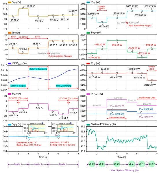
Figure 8. Simulation results of Case 2.
The third case corresponds to the operation of the FPIBC in modes 1, 2, and 3 and the transition between these modes. The proposed converter is completely analyzed under unbalanced and varying load conditions, a sudden rise and drop in solar irradiation, and changes in the ambient temperature, the FP, and OT of the SOFC. The simulation waveforms obtained for Case 3 are shown in Figure 9. As can be seen in Figure 9, the OT and FP of the SOFC are considered constant at 973 K and 1.1 bar until t = 7 s. These parameters change at t = 7 s and decrease to 923 K and 1.0 bar. The solar radiation is 500 W/m2 between t = 1 s and t = 3 s, 800 W/m2 between t = 3 s and t = 5 s, and 300 W/m2 between t = 7 s and t = 8 s. It is assumed that solar power is not available between t = 5 s and t = 7 s. In Case 3, voltage imbalances are observed throughout the simulation due to the unequal distribution of load powers at the output. Load changes occur at t = 3 s, t = 5 s, and t = 7 s. In the time interval of 1–3 s, the FPIBC is operating in mode 2. In this time interval, the PV and SOFC produce power of approximately 1862 W and 4086 W. As the load power demand is 6150 W, a lack of power is supplied by the battery. Therefore, the battery is in the discharging mode between 1 and 3 s. At t = 3 s, the solar irradiation and power demand of the load increase to 800 W/m2 and 6250 W. The FPIBC switches from mode 2 to mode 1. In the time interval of 3–5 s, the produced PV power increases in direct proportion to the rise in solar irradiation and reaches approximately 2974 W with the MPPT controller. The PV current increases from 19.89 A to 31.44 A. Since the total amount of PV and SOFC power is greater than the load demand, the excess power is transferred to the battery. The battery charges with a nominal current of −4.54 A. At t = 5 s, the solar power is not available (the solar irradiation is assumed to be zero). Hence, in time interval of 5–7 s, the FPIBC is in operation mode 3. The power demand of the load (5850 W) is met by the SOFC and the battery. The battery discharges with a current of 13.04 A. At t = 7 s, the solar irradiation is 300 W/m2 and the ambient temperature increases from 25 °C to 35 °C. The power requirement of the load decreases from 5850 W to 4350 W. The FPIBC switches from mode 3 to mode 2. In the time interval of 7–8 s, the SOFC power decreases from 4086 W to 3580 W. The PV power produced is approximately 1080 W at 35 °C and 300 W/m2. The load is fed by the PV, SOFC, and battery. It has been shown that the maximum efficiency is 95.45% while the peak efficiency is 97.28%.
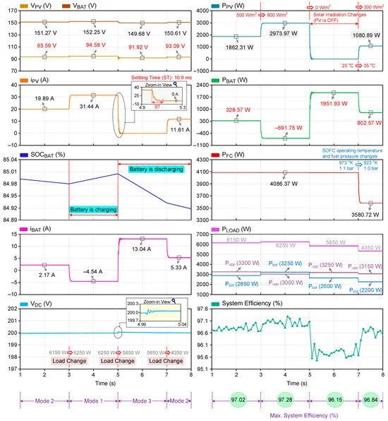
Figure 9. Simulation results of Case 3.
The ability of the FPIBC to mitigate the voltage imbalance at the output terminals in Cases 2 and 3 is illustrated in Figure 10. To overcome the differences between the output voltages, a voltage-balancing circuit is employed. To control the active power switch (Q5) in the voltage-balancing circuit, an algorithm has been developed. The upper and lower side load voltages of the FPIBC are kept almost identical (100 V) owing to the voltage-balancing controller, even though the load distribution is seriously unequal. In Case 2, the output voltages are 92.616 V and 107.084 V between t = 3 s and t = 5 s when the powers of the upper and lower load groups are 3700 W and 3200 W, and the voltage-balancing controller is not enabled. It is obvious that the voltage difference between the output voltages is below 1V when the voltage-balancing controller is activated. The worst-case scenario is considered by assuming a power difference between the loads of 950 W (Pupp = 3150 W and Pbot = 2200 W). The load voltages in that condition (case 3, t = 7–8 s) are measured as 117.779 V and 82.265 V without the voltage-balancing controller. Load voltages of 99.523 V and 100.486 V are achieved when the balancing algorithm is activated. It has been validated that the voltage imbalance is kept below 0.5% in all cases.
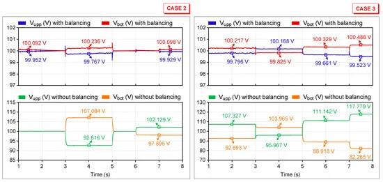
Figure 10. Comparison of the system performance with and without voltage-balancing circuit.
The performance of the proposed system is analyzed using a dynamic load profile, which is modeled by considering the daily local power consumption data in Adana Province, Turkey. Figure 11 shows the hourly power consumption of the load, the cumulative power demanded by the load, and the hourly solar irradiation data in a day. It can be observed from Figure 11 that the power consumption of the local loads is higher during the day than at night. The maximum power demand of the load occurs at 8.2 kW between 12:00 and 13:00, whereas the minimum power consumption is recorded as 1.5 kW between 00:00 and 01:00 at midnight. The daily cumulative power consumption is calculated as 112.7 kW. Fluctuations in solar radiation during the day introduce intermittency in the generated power. The solar radiation is 0 W/m2 between 19:00 and 24:00 and between 00:00 and 07:00. The solar radiation at the beginning of the day at 07:00–08:00 is 300 W/m2, reaching a maximum of 1000 W/m2 at midday (12:00–13:00). Solar radiation gradually decreases in the afternoon, and its daily trend resembles a bell-shaped curve.
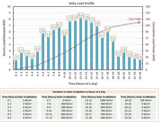
Figure 11. Load profile of hourly and cumulative power consumption values and hourly solar irradiance data in a day.
Figure 12 shows the simulation waveforms of the FPIBC system operating under a daily dynamic load. The power consumption of the load varies between 1.5 kW and 8.2 kW over a 24 h time period. The power produced by the PV system varies depending on the hourly solar radiation with the MPPT controller, and the highest value is 3.7 kW. It is assumed that the SOFC produces almost the same power throughout the day, considering that there is no change in its parameters (fuel pressure or operating temperature), and the OOR controller is enabled. If the total power of the SOFC and PV is higher than the power consumed by the local loads, the battery is charged; if it is lower, the battery supports the system. The negative current and power values in the battery indicate that the battery is charging, whereas the positive values indicate discharging. It can be clearly seen that the dc-link voltage is maintained at 200 V throughout the day.
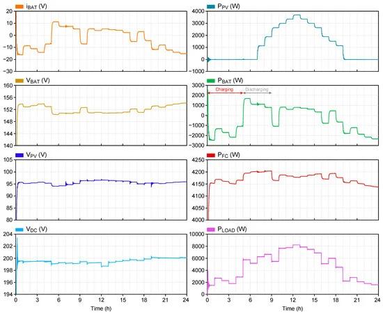
Figure 12. Simulation results of system performance under a 24 h load profile.
Comparison with Other MPCs
Table 4 outlines a comparison of the proposed FPIBC topology with existing MPCs in terms of isolation, bipolar output voltage, power flow direction, number of ports, number of circuit elements, and the achieved maximum efficiency. It can be clearly seen that the FPIBC has the advantage of a bidirectional power flow at the battery port, although the MPCs presented in [6,33,34,44,45] only have a unidirectional power flow between their ports. In addition, the topologies suggested in [2,6,21,32,33,44,46,47] are less reliable because they do not provide isolation. On the other hand, the proposed topology has a bipolar output voltage opportunity, whereas the topologies in [16,18,19,20,21,45,46,47,48,49] have a single output voltage and are not appropriate for BPDCMG applications. The isolated bidirectional three-port converter introduced in [25] has a bipolar output voltage, but its efficiency is low. Compared with the converter in [35], it is obvious that the FPIBC has more ports and a higher efficiency. Moreover, the proposed converter employs fewer active switches and has a higher efficiency than the five-port converter developed in [14]. The proposed system is superior in terms of cost-effectiveness compared to the converter in [14].
Table 4. Comparison of the proposed topology with other MPCs.
5. Conclusions
In this paper, a new and versatile FPIBC configuration that combines two full-bridge converters, a resonant tank, and a voltage-balancing circuit is proposed for BPDCMG applications. The FPIBC differs from many topologies available in the literature in that it has balanced bipolar output voltages and includes a bidirectional battery port. The proposed converter has the following advantages over other MPCs developed for the same purpose in the literature: (i) the capability to integrate multi–input RESs and ESUs into the BPDCMG, (ii) the capability to execute all possible power flow scenarios between the ports, (iii) the capability to suppress voltage imbalances to provide bipolar outputs, (iv) the capability to provide isolation via an HFT, (v) a reduced number of switches, (vi) a high efficiency, and (vii) cost-effectiveness. The PI controller detects voltage imbalances greater than 1V and mitigates adverse effects via a voltage-balancing circuit. Power flow management determines the operation mode by considering the available power of the PV, SOFC, and battery along with the load demand. The performance of the proposed system and its controller under steady-state and transient conditions has been evaluated via simulation studies performed using MATLAB/Simulink software (2022b version). The effectiveness of the proposed FPIBC has been validated through comprehensive case studies involving three different operating modes and dynamic load variations. In addition, the proposed system was tested under a 24 h load profile that varies between 1.5 kW and 8.2 kW. The simulation results revealed that the system has an efficiency of at least 95.37%, while the peak efficiency is 97.28% and the voltage imbalance is maintained below 0.5% (~1V). Consequently, it has been demonstrated that the proposed system operates with a high efficiency, performs all functionalities, such as balancing bipolar output voltages and bidirectional power transfer at the battery port, successfully, and responds to the transient conditions dynamically. The challenges of the proposed FPIBC are the control complexity and modeling of the uncertainty effects of sources, such as the PV, FC, and battery. Future studies will focus on improving the system efficiency, searching for new topologies to reduce the number of active switches, implementing different and effective controllers, and developing a new algorithm to track the maximum power point of the PV system under partial shading conditions.