
Abstract
With the development of communication technology, the interference from passive intermodulation to the communication system has become increasingly severe. Locating the source of passive intermodulation and then repairing or replacing the device experiencing passive intermodulation is a reliable method. Therefore, this paper proposes a dual-frequency signal localization method based on the principle of phase ranging to accurately locate the passive intermodulation sources in RF cables. This method switches the test signal frequency to obtain the phase of passive intermodulation signals at different frequencies to localize the passive intermodulation source. This paper analyzes the principle of the passive intermodulation localization method based on dual-frequency signals, establishes a localization system for experiments, and finally, analyzes the experimental error to propose an optimization strategy. Through experimental verification, this method can stabilize the positioning error of a passive intermodulation source in a transmission line less than 0.06 m. Meanwhile, this method has high positioning accuracy and the advantages of slight computational complexity, fast positioning speed, and only a small number of requirements on hardware resources. It can work in communication scenarios like satellite and base stations, providing a new technical solution for localizing passive intermodulation interference sources in 5G and 6G communication systems.
Keywords: passive intermodulation; dual-frequency signal; RF transmission lines; localization; 5G; 6G
1. Introduction
Passive intermodulation (PIM) interference arises due to nonlinear components in communication circuits [1]. When signals containing more than one frequency pass through a PIM source, the nonlinear components in the communication system cause the signals of different frequencies to modulate each other, generating a series of interfering signals. These interfering signals are known as passive intermodulation products. If the passive intermodulation components fall within the operating bandwidth of the receiver of the communication system, it will interfere with the transmission of information [2,3]. When the input signal is a two-tone signals, the frequency components of the resulting interference signal are similar to those shown in Figure 1.

Figure 1. Spectrogram of the interference signal generated when a two-tone signal passes through a passive intermodulation source.
From Figure 1, it can be seen that the two-tone signals will generate interference signals after passing through the passive intermodulation source. The most severe interference is the third-order passive intermodulation component because the third-order PIM signal is spectrally closer to the carrier; it cannot be easily filtered out by the filter in the receiver. From the point of view of passive intermodulation signals generated by two-tone signals, multi-frequency communication systems will be more seriously affected by passive intermodulation interference because of the complexity of the signal frequency components when there is a PIM source in the system. In addition to the multicarrier communication system, satellite communications, as representatives of the high-power communication system affected by passive intermodulation interference, are also severe due to the more serious complex signal frequency components of passive intermodulation interference. The main reason is that high-power signals are more likely to cause passive intermodulation interference.
Previously, passive intermodulation interference caused many satellite communication accidents, such as the U.S. fleet communication satellites, maritime satellites, European maritime satellites, and international communication satellites, which resulted in severe interference to receivers due to passive intermodulation products [4,5,6,7,8]. The communication system is moving in the direction of high-power, high-frequency, and multicarrier systems, and the interference generated by passive intermodulation can no longer be ignored. And emerging communication technologies such as 5G and 6G need to connect equipment for large-scale connections for massive communication [9,10]. In such a complex communication environment, the impact of passive intermodulation interference cannot be ignored; passive interference will cause all-around interference to the entire communication system. Therefore, a method that can solve the passive intermodulation problem is needed to improve the communication capability of the communication system.
Current research on passive intermodulation is directed toward the generation mechanism, suppression, cancellation, and localization of passive intermodulation. However, because the generation mechanism of passive intermodulation is too complex and uncontrollable, the appearance of PIM interference is inevitable, so it is difficult to directly eliminate or inhibit the generation of PIM [11,12,13]. However, by locating the PIM source in the communication circuit, the device can be targeted for repair and replacement to eliminate and suppress PIM interference. Therefore, the realization of the precise location of the PIM source is an essential prerequisite for stopping and eliminating PIM interference.
The International Electrotechnical Commission (IEC) in [14] proposed two standards for passive intermodulation testing, the reflection and transmission methods, and the system structure of these two methods is shown in Figure 2.
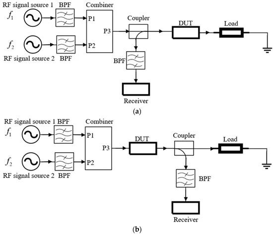
Figure 2. The PIM test standards proposed by IEC are (a) reflective method and (b) transmission method.
There has been a lot of research on passive intermodulation localization techniques. For example, the near-field measurement method mentioned in [15] and the holographic imaging method mentioned in [16] can detect PIM sources. However, these two methods can only locate the PIM sources present in the external space in the wireless communication system. They cannot locate the PIM sources inside the RF (Radio frequency) transmission lines and other waveguide devices [14]. S. Yang proposed a technique based on vibration modulation to localize PIM sources using mechanical loosening [17], such as connectors between RF transmission lines. However, this method can also not localize PIM sources inside RF transmission lines. According to now publicly available academic data, k-space localization techniques [18] and signal phase ranging techniques [19] can effectively localize PIM sources inside RF transmission lines. In engineering, some companies have applied the method of fault point detection in the time-domain reflection technique to PIM source localization [14]. All of these methods can localize PIM sources in RF transmission lines, but all of these methods have drawbacks. For example, in the k-space multicarrier technology [18], the positioning accuracy is limited by the influence of the signal bandwidth [14], and the phase ranging technology of the patent [19] is limited by the impact of the blurring of the signal period, which can only roughly determine the position of the PIM source and cannot pinpoint the exact position of the PIM source. Also, some of the time-domain reflection technology requires a higher hardware cost to achieve a longer measuring distance and a higher positioning accuracy.
On the basis of the above factors, this paper proposes a passive intermodulation localization scheme for dual-frequency signals based on the phase method, which can effectively localize the PIM sources in closed devices such as RF transmission lines. It has the advantages of a simple localization method, high localization accuracy, and a simple hardware system. Experimentally, the positioning error of this method can be stabilized at less than 0.06 m.
This paper is organized as follows. In Section 2, the principle of a phase-based dual-frequency signals is introduced, and the design of the localization system is described. In Section 3, the dual-frequency signals localization technique is experimentally verified, and the experimental data are analyzed to determine the source of error and provide an optimization method. In Section 4, the shortcomings of the localization method are discussed, and conclusions are provided.
2. Fundamentals and Methodology
2.1. Localization Algorithm for PIM Source
The phase method ranging principle is simple, accurate, and efficient and has been applied explicitly in PIM positioning systems. For example, in the patent [19], the authors designed a PIM source localization system based on the phase method, but the system could not localize a passive intermodulation source accurately. The reason for the inability of this method to accurately localize is that the ambiguity of the signal period leads to non-unique ranging results, and only several possible locations of the PIM source can be obtained. The ranging method based on dual-frequency signals proposed in this paper can solve the problems caused by signal period ambiguity. It can yield unique localization results and have high localization accuracy.
The dual-frequency signals ranging technique generates an intermodulation signal reflected to the input port by the two-tone signal passing through the PIM source. The position of the PIM source is determined by analyzing the phase of the intermodulation signal received at the input port. To calculate the position, the frequency of the two-tone signals is adjusted so that the frequency of the intermodulation signal of a given order varies from low to high, and the corresponding phase is obtained. The theory of this method is described and analyzed as follows.
To begin with, we denote the frequency and initial phase of the test signals and the intermodulation signal as respectively. When test signals pass through a PIM source, new frequency components are generated. The delays of the signals under test that occur within the cable under test are denoted as and the delay that elapses via the intermodulation signal reflecting the input port from the PIM source is represented as
If the time required for the test signals to reach the PIM source from the input port of the cable under test is , for the test signals passing through the PIM source, the phase of the (m + n)th-order PIM signals generated is:
where x is the position of the PIM source in the RF transmission line; the above signals propagation process is shown in Figure 3.
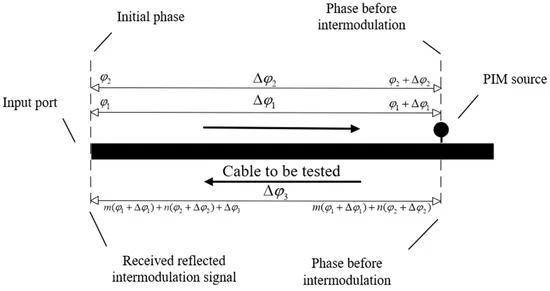
Figure 3. Phase changes in signal transmission.
After the above calculation process, the position of the PIM source in the transmission line can be obtained. Still, due to the phase error the localization result error is expressed in the following equation:
Equation (7) shows that as the frequency of the passive intermodulation signal is higher, the localization result error is more minor. However, the smaller the frequency of the passive intermodulation signal, the shorter the length of the measured transmission line. The relationship between the frequency of the passive intermodulation signal and the maximum ranging range can be expressed in Equation (8) as:
From the above analysis process, it is clear that the frequency of the passive intermodulation signal affects the ranging range and ranging accuracy. When the frequency of the intermodulation signal increases, the ranging accuracy increases, but the range becomes smaller. When the ranging range is smaller than the length of the transmission line, the localization results obtained at this time will not be unique. When the intermodulation signal frequency decreases, the range increases, but the range accuracy decreases. Therefore, using only high-frequency or low-frequency signals for ranging can not meet the requirements of high-precision positioning of the PIM source. For the above problems, the dual-frequency signals localization technique proposed in this paper can effectively solve the contradiction between ranging range and ranging accuracy.
The principle of the dual-frequency signals localization technique is to use a low-frequency signal to determine the approximate location of the PIM source and then use a high-frequency signal to obtain the exact location of the PIM source based on the ranging results of the low-frequency signal.
The localization process of the dual-frequency signals localization technique is as follows. First, use the two-tone signals as the test signal input to the cable under test, and then receive the reflected second-order PIM signal at the input of the cable. Next, calculate the phase value of the second-order intermodulation signal. (This paper uses the second-order PIM signal to locate the PIM source; the PIM signal used in this step of the ranging range should be greater than the length of the transmission line.) Next, the test signal is passed through a standard intermodulation source to obtain a reference intermodulation signal of the same order as the reflected PIM signal. Then, the phase value of the reflected PIM signal is used to subtract the phase value of the reference PIM signal. Finally, the approximate location of the PIM source can be obtained by substituting the phase difference into Equation (9).
where is the current result measured using the low-frequency PIM signal,is the wave speed (The wave speed of the cable used in this paper is 2.45 × 10⁸ m/s, and the wave speeds in all the experiments in Section 3 are 2.45 × 10⁸ m/s), and is the phase difference between the reflected PIM signal and the reference PIM signal.
The ranging signal used in this step is referred to as a low-frequency signal, with the frequency shown in Equation (10):
The principle of low-frequency PIM signal ranging is represented in Figure 4.

Figure 4. Principle of low-frequency signal ranging. This figure represents the phase change caused by a low-frequency signal arriving at the PIM source from the input and then reflecting to the receiver.
At this time, the measured result is not the exact position of the PIM source. The ranging accuracy is still insufficient, so it is necessary to process the localization results of the low-frequency signal. First of all, the localization results of low-frequency signals are processed using rounding:
where represents the wavelength of the high-frequency signal in the next step; the purpose of this step is to obtain the integer multiple of the period that the high-frequency signal passes through in the cable using the estimated position of the low-frequency signal to measure it.
The next step is to range the PIM source using a higher-frequency signal and repeat the above calculation process to obtain the phase difference; the signal propagation process is shown in Figure 5.

Figure 5. Principle of high-frequency signal ranging. This graph represents the phase change and number of cycles caused by a high-frequency signal arriving at the PIM source from the input and then reflecting to the receiver.
Finally, based on the initial phase difference Δφ′">Δ????′ between the high-frequency signal and the test signals, the location of the PIM source can be obtained using Equation (12):
The position x">???? obtained at this point is the exact position of the PIM source. When the phase error is Δφ0">Δ????0, the localization error is:
The above is the whole dual-frequency signal localization method, which can solve the contradiction between high accuracy and long-distance localization.
2.2. Localization System of PIM Source
On the basis of the above analysis, a passive intermodulation localization system based on dual-frequency signals can be designed, as shown in Figure 6. The system uses a two-tone signals as the test signal. A forward coupler is used to couple a portion of the two-tone signals to a reference PIM source and pass it through a low-noise amplifier and band-pass filter to obtain a reference passive intermodulation signal of a specific order. Next, the PIM signal reflected from the cable to be tested is obtained using a reverse coupler and is amplified and filtered for phase identification. Next, the phase difference between the reflected PIM signal and the reference PIM signal is obtained by differential phase discrimination. The phase difference obtained here is not only the direct phase difference from the input port of the cable to the PIM source but also includes the additional phase error introduced by the system; therefore, the system needs to be calibrated to obtain a more accurate phase difference.
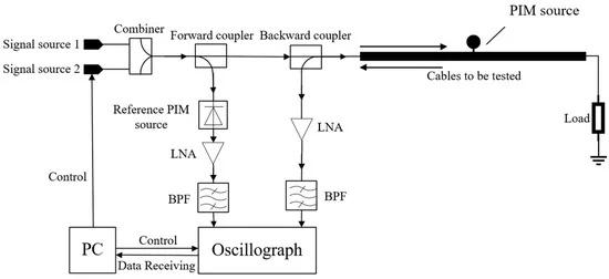
Figure 6. PIM localization system based on dual-frequency signals.
The calibration operation of the system involves calibration using a cable under test with a known PIM source location to obtain the phase error within the PIM positioning system. Then, calibration is performed by subtracting the excess electrical length from each positioning result.
3. Experiments
In this section, the localization capability of the PIM source system based on dual-frequency signals is experimentally verified, and the localization accuracy of this system is shown through several experiments.
3.1. Calibrations
The role of the reference PIM signal in the system is to synchronize with the reflected PIM signal and calculate the phase difference by subtracting the effect of the initial phase of the test signal, but this does not eliminate the impact of additional phase shifts and systematic errors in the system. A calibration method is proposed in this paper to eliminate the phase error in the system. Before the system is positioned, a standard PIM source is directly used as the component under test, and the signal is inputted to the standard PIM source, and then the received phase difference is obtained. At this point, the phase difference is saved directly into the system, and the additional phase shift measured by the calibration here is subtracted from the subsequent positioning results.
This system is calibrated by positioning the transmission line with the known position of the PIM source, obtaining the measured phase difference at that frequency, and saving the measured phase difference in the positioning system at this time. In this paper, the system is calibrated with the location of the standard PIM source at the output port of this positioning system. Because the diode has a nonlinear effect, it can be used to simulate a PIM source in a transmission line, or it can be used as a reference PIM source. The diode HSMS 282C is used in this paper to simulate a PIM source. Figure 7 illustrates the structure of the system calibration.
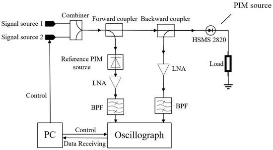
Figure 7. System calibration diagram.
This calibration process minimizes the error introduced by the extra phase of the positioning system, and the additional phase shift of this system at the following frequencies is shown in Table 1.
Table 1. Phase difference obtained after calibration of the positioning system.

3.2. Localizations
This paper uses the diode HSMS 282C to simulate the PIM source. The positioning system is shown in Figure 8. Since this system can only localize a single PIM source, the PIM sources at 1.5 m, 3.0 m, 4.5 m, and 6.0 m are localized sequentially, and the localization results are shown in Table 2.

Figure 8. PIM localization experiment system. The oscilloscope used in the experimental system is LeCroy DDA-3000, the signal source is R&S®SMB100A, and the power supply is from ITECH.
Table 2. PIM source localization results.
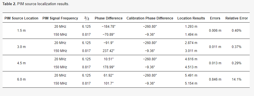
Table 2 shows that the localization error is tiny when the PIM source is located at 1.5 m, 3.0 m, and 4.5 m. However, the error when the PIM source is 6.0 m is enormous. For the PIM source at 6.0 m, if the 6.0 m final localization result in Table 2 is added to the 150 MHz half-wavelength, an accurate result can be obtained. The 20 MHz localization error is too large, causing the period blurring of the 150 MHz signal; the period blurring can be improved by reducing the frequency of the high-frequency signal to improve the accuracy. The ranging results obtained when the high-frequency signal is reduced to 100 MHz are in Table 3.
Table 3. The results of the improved experiments for PIM source localization.
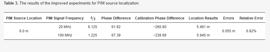
Table 3 shows that the error of the PIM signal source at 6.0 m analyzed earlier is reasonable, and suitable high-frequency signals are an essential condition for accurate PIM measurement. This paper is based on dual-signal ranging, and from the above experimental results, the choice of frequency is crucial for the final positioning accuracy. The difference between the ranging result of the high-frequency signal and the low-frequency signal must not be too significant; that is to say, the size of the frequency of the high-frequency signal should be adjusted moderately along with the ranging result of the low-frequency signal to obtain a reliable and accurate positioning result.
The above experimental results show that the positioning results of high-frequency signals are not necessarily accurate, mainly because the low-frequency signal ranging error may be combined with the blurring of the period of high-frequency signals, which will increase positioning error. The solution to this problem is to reduce the frequency of the high-frequency signal to eliminate the effect of the positioning error of the low-frequency signal on the high-frequency signal.
Based on the above analysis, the frequency value of the high-frequency signal needs to be determined based on the maximum error of the low-frequency signal ranging and the results of the low-frequency signal ranging. In the process of ranging, if the frequency of the high-frequency signal is too low, it will not meet the accuracy requirements; if the frequency of the high-frequency signal is too high, the high-frequency signal will cause cycle blurring due to the ranging error of the low-frequency signal. The ranging error of the high-frequency signal mainly comes from the phase identification error, a parameter that can be known in advance. According to this parameter and the accuracy requirements to set the frequency value of the high-frequency signal, for the positioning system, this value is generally measurable; this paper uses the scheme that the half-wavelength of the high-frequency signal is at least greater than the low-frequency signal error of two times.
The high accuracy obtained in this paper does not depend on the increased complexity of the program; this work employs a simple and fast method to localize and detect PIM sources in RF transmission lines. Due to the method’s simplicity and practicality, the localization system’s design does not require expensive hardware costs, and more accurate localization can be accomplished without complex computational procedures. For the general phase method PIM source localization technique, the time complexity of this method is low. In the patent [19], multiple measurements are also used to obtain the possible position of the PIM source. Still, this method is different from it in that it eliminates the period ambiguity, improves the positioning accuracy, and reduces the computational complexity.
4. Conclusions
From the experimental data, the localization accuracy of this method is high. After many tests, most positioning errors are less than 0.02 m; even if the error is more significant, it is also stable at less than 0.06 m. This is a more considerable performance in the RF transmission line positioning field, which can fully satisfy the positioning of the PIM source in most scenarios.
The published academic literature on PIM source localization techniques inside the device are k-space multicarrier localization, acoustic vibration, and phase difference-based passive intermodulation localization techniques. All of the localization techniques mentioned above can locate the PIM source inside the RF transmission line, and these localization techniques are compared in Table 4.
Table 4. Comparison of PIM source localization techniques for closed devices.
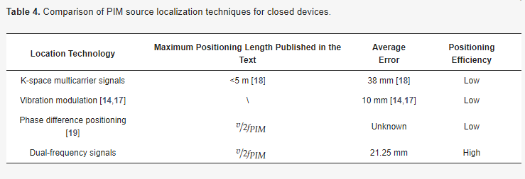
This paper compares and analyzes the maximum positioning length, accuracy, and speed. K-space multicarrier technology can locate multiple PIM sources at the same time. In [18], the average error of the positioning of the PIM sources at different locations is 38 mm. The maximum positioning length of this technology is not discussed in the article, and the full positioning length that appears in the article is used directly for the comparison here. The maximum localization length is used as a basis for comparison. In addition, the main disadvantage of this technique is that it is greatly affected by the signal bandwidth, and if the signal bandwidth is small, the localization accuracy will decrease rapidly, or even the PIM source cannot be localized. The complexity of the k-space localization technique is high, and it needs to rely on many signal phases and amplitudes to construct the k-space transform to obtain the position of the PIM source, so the real-time performance is poorer. The requirements for the hardware system are also greater in number.
The localization technique based on the phase method is more similar to the technique mentioned in this paper, which is based on the phase information of the signal to obtain the position of the PIM source. The difference is that the PIM source position obtained in the patent [19] is the possible position. The precise positional information of the PIM source cannot be obtained directly, mainly because the phase is fuzzy, the number of cycles experienced by the signal in the transmission line is unknown, and the unknown PIM source can only be inferred continuously by switching the frequency several times to obtain the phase value. The method proposed in this paper combines the advantages of a large-ranging range of low-frequency signals and the high-ranging accuracy of high-frequency signals to obtain the precise position of the PIM source. In addition, according to this method, the localization system provided in this paper can complete the ranging work without an expensive hardware system, with low time complexity and high efficiency.
The dual-frequency signals based ranging method proposed in this paper has the advantages of high accuracy, high efficiency, and low cost. However, this method also has some limitations. When there are multiple PIM sources in the RF transmission line, accurate PIM source localization results cannot be obtained, which is the only known disadvantage of this method. The following important research goal is localizing the PIM sources in the transmission line with high efficiency and accuracy.